
Note: This manual may cover
several products or versions of one product.
Other products or versions covered by this manual may still be active.
Model 122 - RS-422/RS-485 to RS-232 Interface Converter
Reference Manual
| Table of Contents |
|
|
|
1.0 General Description 2.0 Specifications 3.0 Installation 4.0 Operation 5.0 Troubleshooting 6.0 RS-232 Pin Number Assignments 7.0 Power 8.0 Help Warranty |
|
|
1.0 General Description
The Model 122, is a card that contains two independent interface converters.
Each converter allows the user to perform interface conversions for RS-232 to
RS-422 or RS-232 to RS-485. Furthermore, the RS-485 mode is selectable for
two-wire or four-wire operation.
Each converter comes equipped with a 5 position dip switch to set the operating
mode and a DTE/DCE switch. The unit also comes equipped with TD and RD LED's,
for each converter, to verify operation. The Model 122 is designed to operate in
the Model 76-3 card cage.
2.0 Specifications
2.1 Interface : Conforms to RS-232, RS-422 and RS-485 specifications.
2.2 Connectors : Dual readout, 15 pin, gold plated card edge connector.
2.3 Data Rate (each converter) : 0 to 115 KBPS
2.4 Switches (each converter) : DTE/DCE switch for reversing TD & RD. 5
position dip switch: sets RS-485 to 2 or 4 wire, RS-422 and termination.
2.5 Indicators (each converter) : TD and RD LED's
2.6 Power : Supplied by Model 76-3 card cage.
2.7 Size : 1"W x 4.5"H x 7"D (25.4mm x 114.3mm x 177.8mm)
2.8 Environment : 0° to 50° C, 5% to 95% relative humidity
3.0 Installation
Note: Prior to installing the unit into the 76-3 Card Cage, make sure that the
power switch on the unit is off (down).
3.1 Card Cage Installation
The connection of the 4 wire line to card cage uses an insulation displacement
connector and connector cover which are included with the card cage. A tool is
also provided for the installation of the wires. The following diagram shows the
pin assignment for the 4 wire line:
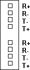
When the RS-232 input signal is - or marking the T+ lead will be high and the T-
will be low. To cause the RS-232 output signal to be - or marking the R+ should
be brought high and the R- should be low.
3.2 RS-422/485 Installation
The Model 122 is designed to interface RS-232 equipment with either RS-422 4
wire, RS-485 4 wire or RS-485 2 wire. The user also has the ability to enable a
220 Ohm terminator when the Model 122 is configured in the 2 wire mode. To set
the dip switches select the option from the following chart.
Note: The B (lower) interface converter on the Model 122 can have the RS-485
mode set to have its transmitter enabled by RTS or can be set to sense when data
is being transmitted by the RS-232 device. The A (upper) interface converter of
the card can be configured only to have its transmitter controlled by the data
signal being transmitted by the RS-232 device.
| TD Control | RTS Control | 220ohms Term | 2 Wire Mode | 4 Wire Mode | ||
|---|---|---|---|---|---|---|
| Mode | SW1 | SW2 | SW3 | SW4 | SW5 | |
| 1. | RS-422 | OFF | OFF | OFF | OFF | ON |
| 2. * | RS-485 4 Wire Transmitter enabled by RTS | OFF | ON | OFF | OFF | ON |
| 3. | RS-485 4 Wire Transmitter enabled by TD | ON | OFF | OFF | OFF | ON |
| 4. * | RS-485 2 Wire Transmitter enabled by RTS | OFF | ON | X | ON | OFF |
| 5. | RS-485 2 Wire Transmitter enabled by TD | ON | OFF | X | ON | OFF |
| On = Closed | Off = Open | |||||
| X = Enable(ON) / Disable(OFF) 220 Ohm Terminator |
| The 220 Ohm terminator should only be selected for use in RS-485 2 wire options. |
| * Modes 2 and 4 are not supported by the A (upper) interface converter of the Model 122 . Both of these switches must be left in the OFF position. |
In addition to the requirements to set the 5 position dip switch the user must
also determine if the Model 122 will look like a DCE or a DTE device. When
configured as a DCE the Model 122 will connect to a DTE device such as a PC or
terminal. When set as DTE the Model 122 will connect to a DCE device such as a
modem.
4.0 Operation
RS-422 - When the Model 122 is configured as an RS-232 to RS-422 converter it
will perform full duplex conversion of the TD and RD signals. The RS-422
equipment is connected to the Model 122 through the 4 pin connector located on
the rear of the 76-3 Card Cage. The R+ and R- are the receiver inputs into the
Model 122 and T+ and T- are the transmitter outputs. When connecting the Model
122 to other RS-422 equipment, the T+ and T- should be one twisted pair while R+
and R- should be another.
RS-485 - In the 4 wire mode the Model 122 has its receiver always ON. The
transmitter of the A (upper) interface converter is turned ON when data is
applied to the Model 122 from the RS-232 device. The transmitter of the B (lower
Interface converter can be controlled in one of two ways. The first is the
transmitter can be enabled when the RTS (or CTS) is enabled or goes high. The
second method is to turn the Transmitter ON when data is applied to the Model
122 from the RS-232 device. Connection to the Model 122 is made to the terminal
block with T+ and T- being the transmit pair and R+ and R- the receive pair.
When operating in the 4 wire mode T+ and T- should be members of the same
twisted pair while R+ and R- are members of the other twisted pair.
The RS-485 two wire mode operates in half duplex mode and uses 1 twisted pair to
transmit and receive. The Model 122 will normally be in the receive mode or
waiting for data from the RS-485 equipment. When the Model 122 wants to transmit
it uses RTS (only the lower interface converter supports RTS) or waits for data
from the RS-232 to enable its transmitters, depending on the mode it is set for.
When operating in the two wire mode the Model 122 uses the T+ and T- for its
connections to the RS-485 device.
5.0 Troubleshooting
The following is a list of possible problems that may arise during the
installation and solutions to these problems:
1. The data being received is garbled?
a) The DTE/DCE switch is not set properly (see section 3).
b) Communication parameters between the equipment that the converter is
connected to are not set the same.
c) T+ and T- are reversed going to R+ and R-. On the converter look at the RD
LED, if it is ON continuously then the leads are reversed.
d) One of the four wires is broken
e) Wires are not paired properly : T+ and T- should be one twisted pair and R+
and R- are the other pair.
2. No data is being received.
a) Customer equipment not connected to the unit.
b) The DTE/DCE switches are improperly set (see section 3).
c) One or more wires between the modems are open.
d) Link connection exceeds maximum specified distance.
If the unit is believed to be defective, operation can be verified if one of the
devices to which the modem is attached is capable of operating in a full duplex
mode (such as a terminal). Connect the unit to the terminal through the RS-232
connector and press the loopback switch in.
If the modem is functioning correctly, any data entered on the keyboard should
appear on the screen.
Note : By switching the card to loopback the unit is reconfigured to operate in
the RS-422 mode. Once the loopback switch is turned off the unit will return to
its original configuration.
6.0 RS-232 Pin Number Assignments
The following pin assignments reference the DB-25 female connector located on
the rear of the 76-3 Card Cage.
| Pin | EIA | CCITT | Name | |
|---|---|---|---|---|
| 2 | BA | 103 | Transmit Data | * |
| 3 | BB | 104 | Receive Data | * |
| 4 | CA | 105 | Request to Send | ** |
| 5 | CB | 106 | Clear to Send | ** |
| 6 | CC | 107 | Data Set Ready | *** |
| 7 | AB | 102 | Signal Ground | Gnd |
| 8 | CF | 109 | Data Carrier Detect | *** |
| 20 | CD | 108.2 | Data Terminal Ready | *** |
* These signals can be reversed using the selector switch.
** Connected together
*** Connected together
7.0 Power
Power for the Model 122 is supplied by the Model 76-3 Card Cage.
8.0 Help
Assistance can be obtained by visiting our
Technical Support
Center.
Warranty
Telebyte warrants the equipment to be free from defects in
material and workmanship, under normal and proper use and in its unmodified
condition, for 12 months, starting on the date it is delivered for use.
TELEBYTE's sole obligation under this warranty shall be to furnish parts and
labor for the repair or replacement of products found by TELEBYTE to be
defective in material or workmanship during the warranty period. Warranty
repairs will be performed at the point of manufacture. Equipment approved for
return for warranty service shall be returned F.O.B. TELEBYTE factory and will
be redelivered by TELEBYTE freight prepaid, except for non- continental U.S.A.
locations. These deliveries will be sent COD freight and import/export charges.
THE ABOVE WARRANTY IS IN LIEU OF ALL OTHER WARRANTIES, EXPRESSED OR
IMPLIED, STATUTORY OR OTHERWISE, INCLUDING ANY IMPLIED WARRANTY OF
MERCHANTABILITY OR FITNESS FOR A PARTICULAR PURPOSE. TELEBYTE SHALL NOT BE
LIABLE FOR ANY DAMAGES SUSTAINED BY RESELLER OR ANY OTHER PARTY ARISING FROM OR
RELATING TO ANY EQUIPMENT FAILURE, INCLUDING, BUT NOT LIMITED TO CONSEQUENTIAL
DAMAGES NOR SHALL TELEBYTE HAVE ANY LIABILITY FOR DELAYS IN REPLACEMENT OR
REPAIR OF EQUIPMENT.
Out of warranty equipment may be returned to the Greenlawn, NY customer service
facility prepaid as described above. Return shipping charges will be billed to
the customer. The repaired unit will have a 90 day warranty. In those cases
where "NO TROUBLE" is found, a reduced charge will be billed to cover handling,
testing and packaging.
Whether in or out of warranty a Return Material Authorization number (RMA) is
necessary. Assistance can be obtained by visiting our
Technical Support
Center.
Document No. 0315-0248/Rev. -