Note: This manual may cover
several products or versions of one product.
Other products or versions covered by this manual may still be active.
Model 273Fiber Optic Mux
|
Table of Contents2.0 Specifications 3.0 Installation |
1.0 General DescriptionThe Model 273 Fiber Optic Mux provides the customer with four, asynchronous, RS-232 ports. Each RS-232 port has one full-duplex, high-speed, data channel and one full-duplex control channel. The four data and four control signals are combined into a composite signal and sent out over an optical fiber. For full-duplex operation, two multiplexers and two optical fibers are required. The maximum concurrent data rate for all eight RS-232 ports, in a full-duplex pair of multiplexers, is 64 kbps. Jumper selection can double the maximum data rate of RS-232 Port 1. In this mode, Port 4 is disabled, enabling Port 1 to communicate at a maximum bit rate of 128 kbps. As an aid to installation and system troubleshooting, the Model 273 has a Loop Test switch on the front panel. Valid receive data on the composite link is indicated by the SYNC LED. Signals on the RS-232 data lines can be monitored via the four Transmit Data LEDs and the four Receive Data LEDs. Included with the Model 273 is an external power transformer and four Modular Adapters. The Modular Adapters provide flexibility when connecting the multiplexer interface to the customer's equipment interface. |
2.0 Specifications2.1 Digital InterfaceElectrical Four RS-232 (signals supported at each port: TD, RD, Control in, Control out, GND) Connectors Four RJ-45 Data Rate Normal speed mode: 0 to 64
kbps (sample rate: 390,625 samples/sec.) 2.2 Optical Interface Connectors ST (trademark AT&T) Power Out +12 dB�W minimum (15.8 �W) into 62.5 /125 � core/clad fiber System Loss Budget 12 dB Wavelength 850 nm, multimode Composite Baud Rate 4.1667 MB 2.3 Indicators 11 LEDs; Transmit Data 1-4, Receive Data 1-4, TEST, SYNC, POWER 2.4 Power Requirements 115 VAC 60 Hz (220 VAC 50 Hz optional) 2.5 Operating Temperature 0o to +50o C 2.6 Size 7 in W x 1.5 in H x 5.5 in D
|
3.0 InstallationInstallation consists of
the following steps:
1. Connect the user equipment to the
Model 273 Digital Interface Ports.
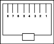
2. Connect the optical fibers to the Model 273. 3. Set Double/Norm speed mode jumper (optional - Factory set to Norm). 4. Set the front panel TEST switch to out. 5. Connect the AC power transformer. Note: A more detailed description of each step of the installation procedure can be found in the text that follows. 3.1 Digital InterfaceThe digital (terminal)
interface to the Model 273 consists of four, eight-pin, RJ-45 connectors
on the rear of the unit. These are labeled Port "1," "2," "3" and "4."
The position of the pins on the RJ-45 connector and their respective
signal names are shown below. |
|||||||||||||||||||||||||
|
|
|
||||||||||||||||||||||||
|
|
|||||||||||||||||||||||||
|
|
||||||||||||||||||||||||
|
|
||||||||||||||||||||||||
|
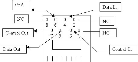
Note: Looking at the
rear of the RJ-45 Plug-A-Verter with wire contacts of the RJ-45 at the
bottom. Pin 1 is always the right-most pin, then count diagonally. |
||||||||||||||||||||||||
|
||||||||||||||||||||||||
|
After determining the
signal requirements of equipment to be connected to the Model 273 and
wiring the Modular Adapters, connect the equipment to the digital I/O
ports of two Model 273s. Ports 1, 2, 3, and 4 of the first unit
communicate with Ports 1, 2, 3, and 4 (respectively) of the other. |
||||||||||||||||||||||||
3.2 Fiber Optic InterfaceConnection between a pair of Model 273s is accomplished through use of two fiber optic cables. These cables are connected to the female ST connectors on the rear of the units. The connectors come with removable plastic caps. The connector labeled "T" is the output of the fiber optic transmitter and the one labeled "R" is the input to the fiber optic receiver. The fibers must be cross-connected between the two units (i.e., the transmitter of one Model 273 must be connected to the receiver of the other Model 273). This is done with both fiber optic cables. The optical system loss
budget of 12 dB is given for fiber optic cables with a core diameter of
62.5 � and a cladding diameter of 125 �. The system loss budget is the
maximum optical loss the Model 273 will work with reliably. This loss is
the total of all the losses in the system, including the fiber, the
connectors and any splices. The units works with other fibers, but in
that case, the loss budget is different. Below are the loss budgets for
the different fibers. |
||||||||||
|
||||||||||
3.3 Double Speed ModePort 1 can be made to communicate data at double the normal bit rate by disabling Port 4. This is called the "Double Mode." This double rate-sampling mode is activated by changing a jumper. In this mode the control signal of Port 1 is still sampled at the same rate, and although the data line of Port 4 is disabled, the control line of Port 4 is still available for general use. To change the Model 273 to
Double Mode the unit must be opened. To do this:
|
|
. 3.4 Test SwitchSet the front-panel Test switch to the OUT position. This is the normal operating mode. 3.5 Power SupplyThe Model 273 is supplied with an external AC power supply. The power supply sent with your equipment is either 115 V or 220 V (determined at time of purchase). Check the label on the power supply to make sure that the power supply voltage matches your AC power line voltage. 1. Connect the small power
plug, on the power supply, to the connector labeled "Power" on the rear
of the Model 273. |
4.0 TroubleshootingAs an aid to installation and system troubleshooting, the Model 273 has a loopback Test switch on the front panel. When the Test switch is pushed in, the Model 273 sends out a signal to the remote unit. Upon receiving this test signal the remote unit turns on its Test LED and sends a test signal back to the originating Model 273. When the originating unit receives this signal it also turns on its Test LED. A successfully completed test verifies correct operation of both composite links of the two units. This test does not interfere with the operation of the data and control lines. The sampling rate of the Model 273 causes some limitations when looping the received signals directly back to the Transmit input at the interface. Some errors may occur if the data or control signals are double sampled. This occurs when the data or control line are sent from one Model 273, received by another Model 273, and looped back directly through the RS-232 interface to the originating Model 273. This only occurs with data at or above 60 Kbps (normal rate) and above 120 Kbps (double rate). The control pins should not be looped at a data rate above 15 Kbps. A valid composite link (Receive Data) is indicated by the Sync LED. When this LED is lit, the composite link from the remote unit's optical transmitter to the corresponding unit's optical receiver is operating correctly. The signals on the RS-232 data lines can be monitored via the four Transmit Data LEDs and the four Receive Data LEDs located on the front panel. These LEDs turn on when the signal at the interface is a high. The on time of the TD and RD LEDs is stretched in order for noisy signals on these lines to be more visible to the human eye. TD blinks when data is being transmitted out of the RS-232 port and RD blinks when data is coming into the RS-232 port. 5.0 HelpAssistance can be obtained by visiting our Technical Support Center. WarrantyTELEBYTE warrants the equipment to be free from defects in material and workmanship, under normal and proper use and in its unmodified condition, for 12 months, starting on the date it is delivered for use. TELEBYTE's sole obligation under this warranty shall be to furnish parts and labor for the repair or replacement of products found by TELEBYTE to be defective in material or workmanship during the warranty period. Warranty repairs will be performed at the point of manufacture. Equipment approved for return for warranty service shall be returned F.O.B. TELEBYTE factory and will be redelivered by TELEBYTE freight prepaid, except for non-continental U.S.A. locations. Non-continental deliveries will be sent COD freight plus import/export charges. The above warranty is in lieu of all other warranties, expressed or implied, statutory or otherwise, including any implied warranty of merchantability or fitness for a particular purpose. TELEBYTE shall not be liable for any damages sustained by reseller or any other party arising from or relating to any equipment failure, including, but not limited to consequential damages nor shall TELEBYTE have any liability for delays in replacement or repair of equipment. Out of warranty equipment may be returned to the Greenlawn, NY customer service facility prepaid as described above. Return shipping charges will be billed to the customer. The repaired unit will have a 90-day warranty. In those cases where "NO TROUBLE" is found, a reduced charge will be billed to cover handling, testing and packaging. Whether in or out of
warranty, a Return Material Authorization (RMA) number is necessary.
Assistance can be obtained by visiting our
Technical
Support Center. |