Note: This manual may cover
several products or versions of one product.
Other products or versions covered by this manual may still be active.
Model 282 Total Interface
|
Table of Contents |
|
1.0 General Description 2.0 Specifications 2.1 Interface 2.2 Connectors 2.3 Isolation 2.4 Data Rate 2.5 Power 2.6 Size 2.7 Environment 3.0 Operation 4.0 Connector Pin Assignment 5.0 Power 6.0 Help Appendix A.- Power Plug Connection Warranty |
|
2.0 Specifications
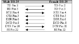
2.1 InterfaceConforms to EIA RS-232 and CCITT V.24 specifications. Pin 2, Transmit Data; Pin 3, Receive Data; Pin 4, Request to Send; Pin 5, Clear to Send; Pin 6, Data Set Ready; Pin 7, Signal Ground; Pin 8, Data Carrier Detect; Pin 20, Data Terminal Ready; and Pin 22 Ring Indicator. 2.2 ConnectorsDTE = DB-25F DCE = DB-25M 2.3 Isolation1000V 2.4 Data Rate0 to 64 kb 2.5 Power110V AC 60Hz (220V 50Hz optional) (-48V DC optional) 2.6 Size2.25" W x 6.75" L x 1" H (57mm W x 171 mm L x 25mm H) 2.7 Environment0 to 50C, 5% to 95% RH (no condensation)
|
3.0 Operation
|
|
||||||||||||||||||||||||||||||||||||||||
|
5.0 PowerThe Model 282 has a built-in isolated DC-to-DC converter. Low voltage AC is supplied by a small wall-mounted transformer. This AC voltage is converted to DC voltage which is used to power the DCE side of the Model 282. The DC voltage is also applied to the isolated DC-to-DC converter, which is also used to power the DTE side of the Model 282.
|
6.0 HelpAssistance can be obtained by visiting our Technical Support Center.
|
Appendix A.
|