![]()
Model 8323 - RS-232 to RS-422 Optically Isolated Interface Converter DIN Rail Mounted
Reference Manual
| Table of Contents |
|
|
|
1.0 Description 2.0 Operating Mode 3.0 Connection / Cabling 4.0 Switch Settings 5.0 Specifications 6.0 Help Warranty |
|
|
1.0 Description
The Model 8323 RS-232 to RS-422 interface converter allows information exchange
in full-duplex mode over two twisted pairs, linking RS-422 equipment with
asynchronous RS-232 equipment, on the DIN rail mounting system.
The RS-422 standard specified by the Electronic Industries Association (EIA)
relates to the electrical characteristics of the generators and receivers used
in a point-to-point system with symmetrical or balanced digital signals. The
RS-422 interface is widespread in industrial environments.
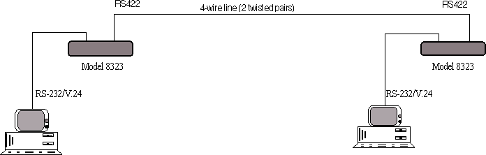
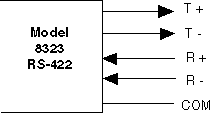
The Model 8323 has one RS-232 I/O configured in DCE mode enabling the reception
of data on the receive pair (RS-422 side) or the transmission of data towards
the RS-422 transmit pair. The RS-422 4-wire connection allows full-duplex
transmission.
2.0 Operating Mode
2-1 Block Diagram:
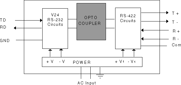
The Model 8323 interface converter provides opto isolation between the RS-232
interface and the RS-422 line by the use of optical couplers. The transmit data
from the RS-232 port is sent over the RS-422 line where it is received by the
far end RS-422 receiver.
2-2 RS-422 4-Wire Connection
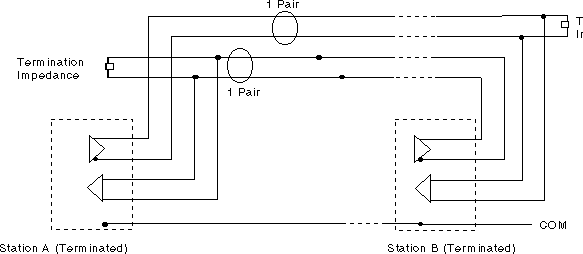
The principle of an RS-422 4-wire link is based upon the use of independent
transmission and reception circuits. Each link requires a termination load on
the receiving end. Each Model 8323 located at the end of the link allows the
insertion of this 120 Ohm termination (RS-422 Standard).
NOTE: The Model 8323 requires the use of twisted pair cabling with a nominal
impedance of 120 Ohms. The use of cable that does not have the correct impedance
or is poorly twisted will produce unreliable operation.
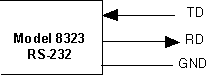
3.0 Connection / Cabling
3-1 RS-232 I/O (DCE mode)
3-2 4-Wire RS-422 I/O

3-3 DIN rail mounting of Model 8323
Top View :
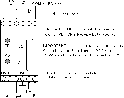
Front View :
4.0 Switch Settings
Dip Switches
The Model 8323 incorporates a group of dip switches. Many of these settings are
fixed in position and marked mandatory and should not be changed. Other switches
that are user selectable are appropriately marked by an X.
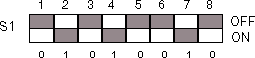
4-1 Dip-Switch S1 :
![]()
|
|
01 : | Mandatory |
|
|
01 : | Mandatory |
|
|
001 : | Mandatory |
|
|
0 : 1 : |
Common not connected to Earth by 100 Ohms Common connected to Earth by 100 Ohms |
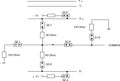
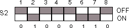
4-2 Dip-Switch S2 :
![]()
|
|
0 : 1 : |
Load Mid-point not connected to Signal Ground Load Mid-point connected to Signal Ground |
|
|
10 : | Mandatory |
|
|
0 : 1 : |
No PULL-UP on Receive - PULL-UP on Receive - in multipoint |
|
|
0 : 1 : |
No PULL-DOWN on Receive + PULL-DOWN on Receive + in multipoint |
|
|
00 : 11 : |
Terminal Loads not connected Terminal Loads connected |
|
|
0 : 1 : |
Common not connected to Loads Load Mid-point towards common |
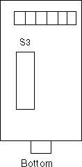
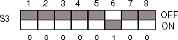
4-3 Dip-Switch S3
Dip switch S3 settings are in mandatory position for FDX operation mode :
00000100.
4-4 Switches and Their Functions
4-5 Factory Settings : Master Mode (dark areas show switch position)
5.0 Specifications
Interfaces : RS-232 (V.24) and 4-wire RS-422 (EIA)/V28 (CCITT)
Transmission mode : Serial Asynchronous, FDX
Transmission speed : Transparent to 115.2 KBPS
Transmission Code : Transparent
Isolation : Via Opto-Couplers
Power : 115 Vac, 60 Hz standard, 230 Vac, 50 Hz optional
Consumption : 2.5 W Maximum
Dimensions : 3.1" x 1.57" x 3.35" (79 x 40 x 85mm)
Environment : Operating Temperature 0° to 50°C, Storage Temperature -20°
to 70°C, Humidity 10% to 90% No condensation
Approvals : CE marked
6.0 Help
Assistance can be obtained by visiting our
Technical Support
Center.
Warranty
Telebyte warrants the equipment to be free from defects in
material and workmanship, under normal and proper use and in its unmodified
condition, for 12 months, starting on the date it is delivered for use.
TELEBYTE's sole obligation under this warranty shall be to furnish parts and
labor for the repair or replacement of products found by TELEBYTE to be
defective in material or workmanship during the warranty period. Warranty
repairs will be performed at the point of manufacture. Equipment approved for
return for warranty service shall be returned F.O.B. TELEBYTE factory and will
be redelivered by TELEBYTE freight prepaid, except for non- continental U.S.A.
locations. These deliveries will be sent COD freight and import/export charges.
THE ABOVE WARRANTY IS IN LIEU OF ALL OTHER WARRANTIES, EXPRESSED OR
IMPLIED, STATUTORY OR OTHERWISE, INCLUDING ANY IMPLIED WARRANTY OF
MERCHANTABILITY OR FITNESS FOR A PARTICULAR PURPOSE. TELEBYTE SHALL NOT BE
LIABLE FOR ANY DAMAGES SUSTAINED BY RESELLER OR ANY OTHER PARTY ARISING FROM OR
RELATING TO ANY EQUIPMENT FAILURE, INCLUDING, BUT NOT LIMITED TO CONSEQUENTIAL
DAMAGES NOR SHALL TELEBYTE HAVE ANY LIABILITY FOR DELAYS IN REPLACEMENT OR
REPAIR OF EQUIPMENT.
Out of warranty equipment may be returned to the Greenlawn, NY customer service
facility prepaid as described above. Return shipping charges will be billed to
the customer. The repaired unit will have a 90 day warranty. In those cases
where "NO TROUBLE" is found, a reduced charge will be billed to cover handling,
testing and packaging.
Whether in or out of warranty a Return Material Authorization number (RMA) is
necessary.
Assistance can be obtained by visiting our
Technical Support
Center.
Document No. 0315-0257/Rev. B
| Model | Product Info |
|---|---|
| 8323 |
|
