Note: This manual may cover
several products or versions of one product.
Other products or versions covered by this manual may still be active.
Model 78X/278XSeriesT1/E1
|
1.0 IntroductionThe Telebyte Model 78X Series is a family of high performance, extremely reliable, stand-alone fiber-optic modems, with each model offering subtle differences designed to meet unique application requirements. The Telebyte Model 78X Series Fiber-Optic Modems are well suited for applications that include the extension of T1/E1 transmission distance for LAN or video conferencing, connecting distributed channel bank networks and providing error-free Internet service from a local ISP. The use of fiber optics as a cabling medium has several advantages, including data line security, total electrical isolation, lightning/surge protection and EMI/RFI immunity. Note:
Telebyte Model 78X/278X Series Definition Models 781 and 783 provide the same functional performance, but are compatible with single-mode fiber cables and offer operation over distances of 14km. Models 784 and 785 are fiber-optic modems designed with FC connectors. These units offer enhanced performance due to their optic technology, and support operation over distances up to 29km. The chart that follows
provides an overall view of the functionality and specifications of each
model in the Telebyte Model 78X Series: |
|
||||||||||||||||||||||||||||||||||||||||||
|
Note: All of these
units are also available in a rack-mount configuration as Models 2780,
2781, 2782, 2783, 2784 and 2785, respectively. The basic card cage rack
for the 278X Series is the Model 2200, and is available with either
single or dual redundant power supplies for 110/220 Volt AC, 50/60 Hz,
or _48 Volts DC. The chart below provides basic card cage
specifications. Please consult the Telebyte catalog or speak with your
Telebyte representative for additional information. (Refer to the
Telebyte Model 78X/278X Series Definition, shown previously in this
document). |
||||||||||||||||||||||||||||||||||||||||||
|
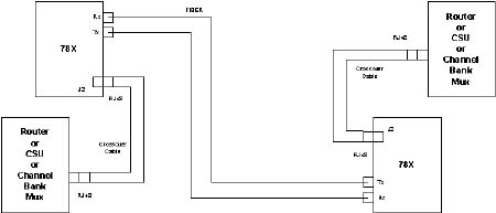
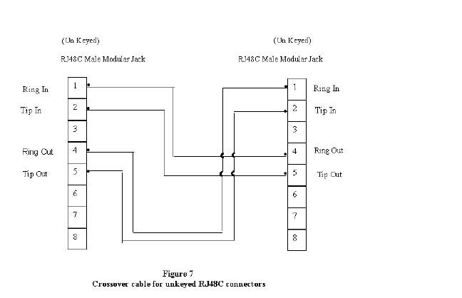
2.0 Operating ModesThis section describes the various operating modes of the Model 78X/278X Series Fiber-Optic Modems. Each unit is equipped with several switches that must be set properly to control the desired operation of the fiber-optic modem. These switches and their functions are described in this section. Typical Application Diagram The following figure illustrates a typical application for the Telebyte 78X/278X units. This is a short-haul application which implies the lengths of the crossover cables are less than 133 feet. All units are shipped with short-haul default settings (see diagram for details). Note: Please refer to
section 6.0, "Factory Default Settings" to view default settings for E1.
Refer to the remainder of this section for information concerning switch
settings. |
|
|
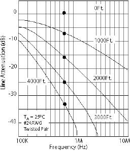
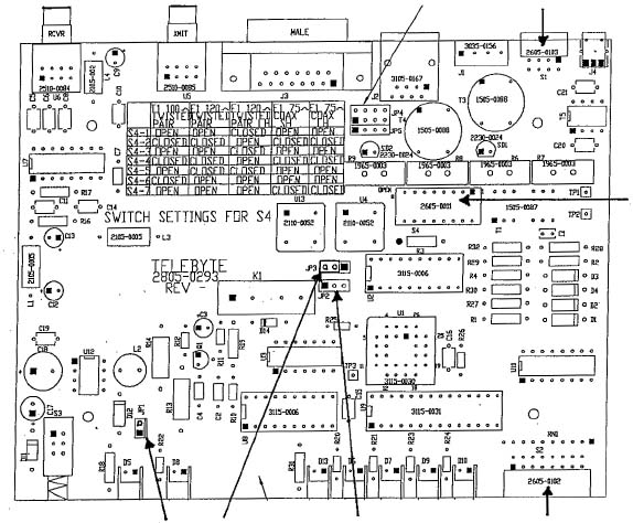
2.1 Line Length—Switch S1Tables 1 and 1A show the
appropriate S1 switch settings that allow optimal transmission and
reception signals. The T1 and E1 jumper formats should be set as shown
below: |
|||||||||||||||||||||||||||||||||||||||||||||||||||||||||||||||||||||||||||||
|
|||||||||||||||||||||||||||||||||||||||||||||||||||||||||||||||||||||||||||||
|
T1 modes are available only on Models 780 and 781. E1 modes are used on Models 782 and 783. Model 780 and 782 utilize multi-mode fiber, whereas Models 781 and 783 utilize single-mode fiber. (This same information applies to Model 278X counterparts.) Table 1
|
|||||||||||||||||||||||||||||||||||||||||||||||||||||||||||||||||||||||||||||
|
· For "S1-1 Off" up to
36 dB of gain may be applied. *For use with 100-Ohm #24 AWG twisted-pair wire. |
|||||||||||||||||||||||||||||||||||||||||||||||||||||||||||||||||||||||||||||
|
|
||||||||||||||||||||||||||||||||||||
|
|
||||||||||||||||||||||||||||||||||||
|
Table 1A
|
||||||||||||||||||||||||||||||||||||
2.2 Line Protection SwitchProtection requirements for T1 equipment are specified in FCC Part 68, UL 1459, Bell Core TR-TSY-000007 and AT&T publication 62411. Similar protection circuitry is suggested for E1 applications in ETS 300 046-3 and ITU K17-K20. Switch S4 implements the appropriate protection circuit for the 78X/278X Series. The following chart identifies the different line conditioning settings necessary for proper operation. |
||||||||||||||||||||||||||||||||||||||||||||||||
|
||||||||||||||||||||||||||||||||||||||||||||||||
2.3 Operational and Diagnostic SettingsTable 2 shows the diagnostic and operational modes controlled by Switch S2, as well as LED indicator illumination. With respect to data format, Model 78X/278X Series Fiber-Optic Modems can be configured to work with either the AMI data format or B8ZS/HDB3. Table 2 shows the switch settings. Table 2
|
|
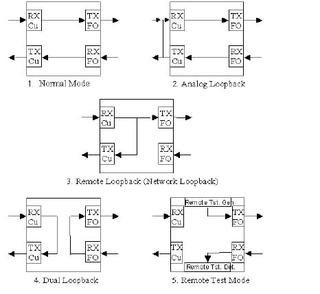
The Model 78X/278X Series test functions are described in the following paragraphs. They are controlled by Switch S2 on the front panel. Refer to Figures 1 through 5 for illustrations and descriptions of each mode. |
|
|
|
Normal Mode Data is passed from the copper RX side to the fiber TX side. Data from the fiber RX side is passed to the TX copper side. If enabled by S2, Network Loopback can be activated. Analog Loopback Data from the fiber RX side is transferred to the copper TX side, and is then routed to the copper RX side. Input data to the RX copper side is disabled. Remote Loopback (Network Loopback) Data from the copper RX side is transferred to the copper TX side, as well as to the fiber TX side. Input data from the fiber RX side is disabled. This mode may also be activated by a Network Loopback command if enabled by Switch S2.
|
|
Dual Loopback Data from the copper RX side is transferred to the copper TX side. Data from the fiber TX side is transferred to the fiber RX side. No data is transferred between the copper and fiber sides. Remote Test Mode Activates the internal remote test generator, which transmits a unique pattern on the fiber TX side that initiates the Remote Test Mode on the far-side unit. Upon successful operation, both the local and remote units light the "Fiber Diagnostic" LED. These test functions are summarized in Table 3: Table 3
|
|||||||||||||||||||||
|
·
Transmit "All Ones:" An
"all-ones" pattern is sent from the copper TX side. Data from the fiber
RX side is disabled. Copper RX data is passed to the fiber TX side. These test functions are summarized in Table 4: Table 4
|
|||||||||||||||||||||
|
|
2.4 Special Testing ModesThe Model 78X/278X Fiber-Optic Modems are capable of performing specialized test functions. This is accomplished by manipulating Switch S2 to insert Bipolar Violations and Logic Errors. Please refer to Tables 3 and 4 for the switch settings for each testing mode. Bipolar Violation Insert: Bipolar violation insert is available in all modes except when in Remote Loopback, or when Network Loopback is active. To insert bipolar violations for 20 microseconds, turn Switch S2-6 ON and then OFF. Logic Error Insertion: Forces an error in the QRSS mode in order to test error detection logic. To induce a logic error, back out the FO RX connector until counting starts. Please refer to the section 5.0, "Performing a Functional Test" for step-by-step instructions on how to execute the special testing modes.
2.5 Jitter AttenuatorThe Jitter Attenuator control in the Model 78X/278X Series of Fiber-Optic Modems offers users control over the internal logic, which impacts how the modem processes data. The user can select from any of the three setting combinations shown in Table 5: Table 5
|
||||||||||||||||||
2.6 LED IndicatorsThe Model 78X/278X Series Fiber-Optic Modems have seven LED indicators on the front panel. The function of these indicators is shown in Table 6: Table 6
|
||||||||||||||||||
|
Table 7
l = LED ON |
||||||||||||||||||||||||||||||||||||||||||||||||||||||||||||||||||||||||||||||||||||||||||||||||||||||||
|
Table 8
|
||||||||||||||||||||||||||||||||||||||||||||||||||||||||||||||||||||||||||||||||||||||||||||||||||||||||
|
|
||||||||||||
|
|
||||||||||||
|
|
||||||||||||
|
4.0 SpecificationsElectrical Interface, T1: Electrical Interface, E1: Optical Interface: Multi-Mode:
Single-Mode:
Connectors: FC Cable: 9/125 um single-mode Diagnostic Capability: Dual Loopback:
Switch selectable Special Functions: Alarm Functions: Power Failure: The card cage provides both visual and audible alarms in the event of a power failure. The power supply for both the AC and DC power supplies consist of dual units. Therefore, a supply failure in a single power supply version of the card cage will still be detectable. The standalone unit has a "Power On" LED. Electrical Signal Loss: "Copper Active" LED goes off in an alarm condition. Also activates visual and audible alarms in the card cage. Optical Signal Loss: "Fiber Active" LED goes off in an alarm condition. Also activates visual and audible alarms in the card cage. Relay Contact: Card cage provides
a dry contact closure, Form A, when an alarm condition is present.
|
5.0 Performing A Functional TestTelebyte Model 78X/278X Series Fiber-Optic Modems can be tested according to the procedure described below. The following equipment is required: · One fully-operational Model 78X/278X
Fiber-Optic Modem Test Procedure 1. Connect a fully-operational Model 78X/278X Series Fiber-Optic Modem (referred to as "the Reference Unit") of the same type as the unit to be tested (referred to as "the Unit Under Test") with the appropriate connector cable type. 2. Set the Reference Unit for unframed "all ones" (S2-4 ON and S2-5 OFF). 3. Set the Unit Under Test in the Remote Loopback Mode (S2-2 ON and S2-3 OFF). Do not connect a fiber jumper cable between the Fiber-Optic TX and RX ports at this time. 4. Observe that on the Reference Unit, the "Power," "Copper Active," "Copper Loopback" and "QRSS" indicators are lit. Observe that on the Unit Under Test, the "Power," "Copper Active" and "Network Loopback" indicators are lit. 5. Next, change the settings on the Unit Under Test to the default positions and connect a fiber jumper cable between the Fiber-Optic TX and RX ports. 6. Observe that on the Reference Unit, the "Power," "Copper Active," "Copper Loopback" and "QRSS" indicators are lit. Observe that on the Unit Under Test, the "Power," "Copper Active" and "Fiber Active" indicators are lit. 7. Next, set the Reference Unit for the QRSS Generator Mode (S2-4 OFF and S2-5 ON). The Unit Under Test should still be in its default positions and the fiber jumper cable connected as before. 8. Observe that on the Reference Unit, the "Power," "Copper Active," "QRSS" and "Network Loopback" indicators are lit. Observe that on the Unit Under Test, the "Power," "Fiber Active" and "Copper Active" indicators are lit.
|
6.0 Factory Default SettingsYour Telebyte Model 78X/278X Series Fiber-Optic Modem ships with the following T1 and E1 Factory Default Settings: 6.1 T1 Factory Default Settings |
||||||||||||||||||||||||||||||||||||||||||||||||||||||||||||||||
|
||||||||||||||||||||||||||||||||||||||||||||||||||||||||||||||||
6.2 E1 Factory Default Settings |
||||||||||||||||||||||||||||||||||||||||||||||||||||||||||||||||
|
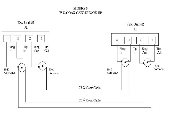
7.0
System
Interconnection Diagrams
|
|
|

|
|
|
|
|
|
|
|
|
9.0 HelpAssistance can be obtained by visiting our
Technical Support
Center. WarrantyTelebyte warrants the equipment to be
free from defects in material and workmanship, under normal and proper
use and in its unmodified condition, for 12 months, starting on the date
it is delivered for use. TELEBYTE's sole obligation under this warranty
shall be to furnish parts and labor for the repair or replacement of
products found by TELEBYTE to be defective in material or workmanship
during the warranty period. Warranty repairs will be performed at the
point of manufacture. Equipment approved for return for warranty service
shall be returned F.O.B. TELEBYTE factory and will be redelivered by
TELEBYTE freight prepaid, except for non- continental U.S.A. locations.
These deliveries will be sent COD freight and import/export charges.
|