|
Table of Contents1.0 General Description 1.1 DataSpy Feature 2.0 Specifications Interface Connectors Switches Indicators Power Size Environment
3.0 Installation 4.0 Operation 5.0 Troubleshooting 6.0 Connector Pin Assignments 7.0 Power 8.0 Help |
1.0 General DescriptionThe Model 65A is a small, versatile, RS-232 to Current Loop Converter for use with computer peripherals such as teletypes or CRT terminals that require interfacing via 20-mA (or 60-mA) current loops. The Model 65A includes switch selection of all operating modes. The switchable parameters include loop type, active or passive, and transmission protocol (half or full duplex). An I/O selection switch is included to allow both DTE and DCE devices to be accommodated (e.g., reversing Pins 2 and 3 of the RS-232 connector). The Model 65A is directly
interfaceable to standard teletypes and 20-mA drives. It also accepts
20-mA or 60-mA loop currents. Both units operate from DC to 9.6 kbps. In
the passive mode, the units provide total electrical isolation between
devices. 1.1 DataSpy FeatureYour new Telebyte product
incorporates the Patent Pending DataSpy feature - an LCD display
designed to assist in the initial installation and check out and to act
as a performance monitor. In the event of a system problem, it provides
information about the status of the local link. |
|
|
|
The Telebyte logo displayed on the LCD screen indicates that the unit is powered (see Figure 1). For power-stealing devices such as a modem, it is an indication that sufficient power is being applied to operate the device. The LCD display uses less than 1 mW of power. The data display on the LCD
consists of graphical representations for TD (Transmit Data) and RD
(Receive Data). Each of these signals is displayed as a bit change
waveform would appear on an oscilloscope. Ordinarily, TD and RD are low
or a minus voltage in the quiescent state. When data is transmitted, the
transmit signal is brought high to a positive voltage. These two signal
states are displayed on the LCD by either a low segment or a high
segment. The low segment represents the negative voltage (the mark
condition) while the upper segment represents a positive voltage (the
space condition). The vertical bar connecting the lower segment to the
upper segment is always on when power is applied. If the transmit signal
is in the quiescent state (continuously low) only the lower segment is
illuminated. This is an indication of a constant negative state. If the
transmit or receive inputs to the device are streaming (in the positive
mode continuously) the LCD display shows the vertical segment and the
upper segments only. For cases where there is valid data transmission,
both the upper and lower segments are displayed simultaneously. A
variation in display intensity between lower and upper segments gives
the user a perception of the amount of data being transmitted. |
|
|
|
The LCD display also
presents the status of the following control signals: CTS, RTS, DSR,
DCD, and DTR. These signals are displayed as mnemonic symbols composed
of three letters - each on the bottom line of the display. The presence
of the three-letter mnemonic indicates that the respective control
signal is high or positive. If the control signal is negative, the
three-letter mnemonic is not displayed. For most full-duplex data-only
modems, CTS and RTS are connected together while DSR, DCD, and DTR are
connected together. For hand-shaking modems there is a relationship
between various control signals on both ends of the link. This
relationship is dependent upon which control signals are utilized. The
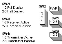
DataSpy LCD display helps to verify correct operation. 2.0 SpecificationsInterfaceConforms to RS-232 and CCITT V.24 specifications. Pins 2 and 3 (Transmit and Receive Data) are switch selectable (reversible). Pin 7 is Signal Ground. ConnectorsRS-232; DB-25M Current Loop Five-position screw terminal SwitchesDCE/DTE: Allows selection of I/O lines for interfacing to a modem or a terminal type device. Half/Full Duplex: Allows selection of either non-simultaneous, two-way transmission without local echo. Active/Passive: Allows
selection of power source (current) for loop operation. Active utilizes
internal power for operation whereas Passive requires the user to
provide a power source in the external loop. The transmitter and
receiver can be individually configured for active or passive. |
IndicatorsLCD display for data, five control signals and power. Power110 V, 60 Hz or 220 V, 50 Hz (optional) Size2 in W x 4.15 in L x .79 in H (50.8 mm x 105.4 mm x 20.1 mm) Environment0� to 50� C, 5% to 95% relative humidity, non-condensing
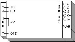
3.0 Installation3.1 Digital InterfaceThe digital interface for the Model 65A converter is a male DB-25, 25-pin connector. 3.2 Current LoopThe current loop interface is a variable depending on the type of device being interfaced and whether a "floating" interface is required. Four typical installations are described in the following text. This should cover virtually all cases. The five connection points
on the Model 65A are K+, K-, G, C+, and C. The K contacts are output
connections whereas the C contacts are input connections. G is Signal
Ground. |
|
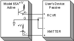
1. Half Duplex - Active Loop
|
|
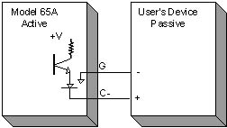
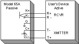
2. Half Duplex - Passive Loop
|
|
3. Full Duplex - Active Loop
|
|
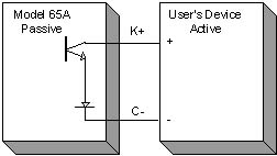
4. Full Duplex - Passive Loop
|
|
The Model 65A can be configured to operate in either half or full duplex and the transmitter and receiver can operate as either active or passive.
|
4.0 OperationThe Model 65A is supplied with a switch that allows the reversing of Pins 2 and 3 of the RS-232 connector. When the switch is in the DTE position, Pin 2 of the EIA connector is an output (transmit-to-host device). Thus, Pin 3 is input. When the switch is reversed to the DCE position, the connectors are reversed (Pin 2 is an input and Pin 3 is an output). When interfacing to a CRT terminal, the switch should be set to DCE. After the above selection has been made, the Half/Full and Active/Passive switches must be set. Refer to section 3.0, "Installation" to determine the configuration required and set the Duplex and Loop switches accordingly. The K connections for
the converters are outputs to drive signals of the Model 65A. K+ is the
collector of the transistor whereas K- is the emitter of that
transistor. In the Passive mode, the transistor is floating; the user
must supply a source of power. In the Active mode, the Model 65A
provides a positive voltage (approximately +12 V) through a 560-W, �W,
resistor to the K+. Collector, contact and current are then available at
the K- contact. |
|
Problem: No data is received. Suggested Reason:
The converter may now be tested by providing the "loopback" connections as follows: Jumper K- to C+ For this test set the switches as follows: DTE/DCE: DCE If the converter is functioning
correctly any data entered on the keyboard of the terminal appears on
the screen. |
6.0 Connector Pin Assignments |
|||||||||||||||||||||||||||||||||||
|
|||||||||||||||||||||||||||||||||||
|
* These signals can be
reversed using the selector switch. 7.0 PowerThe Model 65A is powered by a small, wall-mounted power supply that supplies 12 VDC @ 500 mA. Note: The power
supply must be connected to the Model 65A, through the 1.3 mm connector
located on the side of the unit, prior to plugging the power
supply into the wall. 8.0 HelpAssistance can be obtained by visiting our
Technical
Support Center. WarrantyTELEBYTE warrants the equipment to be free from defects in material and workmanship, under normal and proper use and in its unmodified condition, for 12 months, starting on the date it is delivered for use. TELEBYTE's sole obligation under this warranty shall be to furnish parts and labor for the repair or replacement of products found by TELEBYTE to be defective in material or workmanship during the warranty period. Warranty repairs will be performed at the point of manufacture. Equipment approved for return for warranty service shall be returned F.O.B. TELEBYTE factory and will be redelivered by TELEBYTE freight prepaid, except for non-continental U.S.A. locations. Non-continental deliveries will be sent COD freight plus import/export charges. The above warranty is in lieu of all other warranties, expressed or implied, statutory or otherwise, including any implied warranty of merchantability or fitness for a particular purpose. TELEBYTE shall not be liable for any damages sustained by reseller or any other party arising from or relating to any equipment failure, including, but not limited to consequential damages nor shall TELEBYTE have any liability for delays in replacement or repair of equipment. Out of warranty equipment may be returned to the Greenlawn, NY customer service facility prepaid as described above. Return shipping charges will be billed to the customer. The repaired unit will have a 90-day warranty. In those cases where "NO TROUBLE" is found, a reduced charge will be billed to cover handling, testing and packaging. Whether in or out of warranty, a Return Material Authorization (RMA) number is necessary. Assistance can be obtained by visiting our Technical Support Center.
|